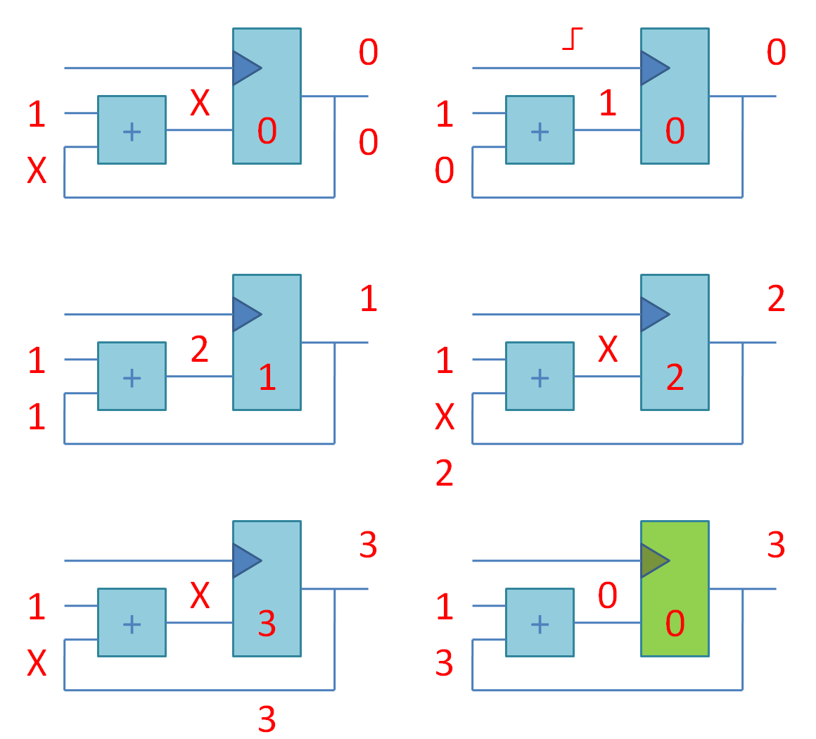
April 24-29 in Kiev will be a series of seminars for students who will not look like ordinary classes with embedded processors, which are standardly used by Lego / Arduino / Rasberry Pye. The main focus of the seminars is not to teach programmers how to program, but to show how the processors are designed internally. It’s like the difference between “learning to drive a car” and “learning how to design an engine”. At the seminars, students will use Verilog’s language description language and logical synthesis, technologies that developers of digital microcircuits use in Apple, Samsung and other electronic companies.
The main official page of the seminar, in the same place registration.
For exercises we use cards with FPGA – matrices of logic elements with a variable function (this is not the usual “processor + memory”). FPGAs have long been used to train students in designing electronics at Stanford and MIT, and more recently in Russian and Ukrainian universities. Using FPGAs for teaching students is an experiment, and you have a chance to participate in it. To facilitate the input to Verilog and FPGAs, we will first deal with small-scale integration circuits on low-profile prototyping boards. Next, we will be working on FPGAs and on the last day of the workshops we will compare the FPGA design with the microprocessor programming for the Internet of things.
You will finally see what happens between the transistor and Arduino, in an area where students rarely look!

The program for senior students and junior students
Monday, April 24th. We begin the path to FPGA: combinational logic and binary arithmetic on microcircuits of small degree of integration
Place: Student space Belka KPI
- 16: 00-17: 00 Alexander Barabanov, KNU. From physics to logic.
- What is current, voltage and resistance.
- How to build a breadboard.
- Exercise 1. The first circuit with battery, LED and resistor. Why include a resistor in a circuit with an LED.
- What are transistors and how are the logical elements constructed of them.
- Exercise 2. Observe the operation of the transistor.
- 17: 00-18: 00 Yuri Panchul, Imagination Technologies. Boolean logic algebra, logical elements AND-OR-NOT.
- Exercise 3. Each student is given a personal logic chip series CMOS 4000, with a technical description from the manufacturer, with the task of drawing a truth table, demonstrate its work and verbally describe the function . The logical elements are AND, OR, XOR, NOR, NAND with a different number of inputs.
- Exercise 4. We study what pull-up resistors are and why they are needed. Add to the Exercises 3 buttons and pull-up resistors.
- 18: 00-19: 00 Binary arithmetic, addition and multiplication.
- Exercise 5. Each student is given an adder CMOS 4008. Demonstration of the adder on the breadboard.
- 19: 00-21: 00 Additional exercises for those who have coped with exercises 1-5 and do not want to go home.
- Exercise 6. The seven-segment indicator and its driver, as an example of a combination scheme. Output of the result of the adder on the seven-segment indicator.

Tuesday April 25th. We add memory: Sequential logic on microcircuits of small degree of integration.
- 16: 00-16: 30 Yuri Panchul. Sequential logic is what makes a computer “smart”, it gives it memory and the ability to repeat operations.
- 16: 30-17: 00 Yuri Panchul and the KPI instructors.
- What is the D-trigger.
- Exercise 7. Connect the clock generator based on the 555 timer to the D flip-flop and examine the work of the chart.
- 17: 00-19: 00 More complex elements of sequential logic.
- Exercise 8. Shear register and moving lights.
- Exercise 9. Counter with status output to the seven-segment indicator.
- 19: 00-21: 00 Eugene Short, KPI. Additional exercises for those who have coped with exercises 6-8 and do not want to go home.
- Exercise 10. Let’s investigate the clock generator based on the 555 chip timer. We observe how the period of the clock frequency varies depending on the resistance of the resistors and capacitance of the capacitor.

Wednesday April 26. Combination logic and binary arithmetic on Verilog and FPGA.
Place: Student space Belka KPI.
- 16: 00-16: 30 Yuri Panchul, as well as instructors from the KPI, KNU. Fast entry into the Verilog hardware description language and use of logical synthesis for FPGA / FPGA. We consider only combinational logic.
- 16: 30-17: 00 Instructors from the KPI, KNU. Combination logic on Verilog.
- Exercise 11. Repeat exercise 2 (logic elements) on the FPGA using the Digilent CMOD A7 35T: Breadboardable Artix-7 FPGA Module.
- Exercise 12. We deduce the first letters of our name and surname on the seven-segment indicator, switching between them using the button.
- Exercise 13. Repeat Exercise 3 (adder) on the FPGA. The result is output to a seven-segment indicator.
- 19: 00-21: 00. Additional exercises for those who have coped with exercises 9-11 and do not want to go home.
- Exercise 14. Hierarchy of modules. Construction of multiplexers with submodules.
- Exercise 15. Simulation of Verilog code without FPGA. We create an environment for verifying the operation of the scheme described in Verilog. We use the simulator Icarus Verilog for modeling and the GTKWave program for viewing time charts.
Example code in Verilog hardware description language, which is translated (synthesized) into the scheme:
 module counter
(
    Input clock,
    Input reset_n,
    Output reg [31:0] count
);

    Always @ (posedge clock or negedge reset_n)
    Begin
        If (! Reset_n)
            Count <= 32'b0;
        Else
            Count <= count + 32'b1;
    End

Endmodule

// ------------------------------------------------ ----------------------------

Module seven_segment_display_driver
(
    Input [3:0] number,
    Output reg [6:0] abcdefg
);

    // a b c d e f g dp Letters from the picture
    // 7 6 4 2 1 9 10 5 Conclusions of the 7-segment indicator
    // 7 6 5 4 3 2 1 PIO signal outputs to FPGAs

    // --a--
    // | | | | |
    // f b
    // | | | |
    // --g--
    // | | | |
    // e c
    // | | | |
    // - d--

    Always @ *
        Case (number)
        4'h0: abcdefg = 7'b1111110;
        4'h1: abcdefg = 7'b0110000;
        4'h2: abcdefg = 7'b1101101;
        4'h3: abcdefg = 7'b1111001;
        4'h4: abcdefg = 7'b0110011;
        4'h5: abcdefg = 7'b1011011;
        4'h6: abcdefg = 7'b1011111;
        4'h7: abcdefg = 7'b1110000;
        4'h8: abcdefg = 7'b1111111;
        4'h9: abcdefg = 7'b1111011;
        4'ha: abcdefg = 7'b1110111;
        4'hb: abcdefg = 7'b0011111;
        4'hc: abcdefg = 7'b1001110;
        4'hd: abcdefg = 7'b0111101;
        4'he: abcdefg = 7'b1001111;
        4'hf: abcdefg = 7'b1000111;
        Endcase

Endmodule

// ------------------------------------------------ ----------------------------

Module top
(
    Input CLK, // Clock signal 12 MHz
    Inout [48:1] pio // GPIO, General-Purpose Input / Output
);

    Wire reset_n =! Pio [8];

    Wire [31:0] count;

    Counter counter_i
    (
        .clock (CLK),
        .reset_n (reset_n),
        .count (count)
    );

    Seven_segment_display_driver display_driver_i
    (
        .number (count [26:23]),
        .abcdefg (pio [ 7: 1])
    );

Endmodule
Thursday, April 27th. Sequential logic and finite state machines on Verilog and FPGA.
Place: Student space Belka KPI.
- 16: 00-17: 00. Yuri Panchul. Sequential logic for Verilog, finite state machines, the concept of RTL (register transfer level) methodology, signal propagation delays and restrictions on the procedure for synthesizing digital circuits, determining the maximum possible clock frequency of the digital circuit.
- 17: 00-19: 00. Instructors from KPI, KNU. Sequential logic on Verilog.
- Exercise 16. A counter with a status output to a seven-segment indicator. Implementation of Exercise 9 on FPGA.
- Exercise 17. Shear register and moving lights. Implementation of Exercise 8 on FPGA.
- Exercise 18. Generation of sound tones of various frequencies and their superposition.
- 19: 00-21: 00. Additional exercises for those who have coped with exercises 17-18 and want to work further.
- Exercise 19. “The snail smiles”: an example of a finite automaton.
- Exercise 20. We construct an arithmetic pipeline. I use the simulator Icarus Verilog to establish the work of sequential circuits.

Friday, April 28th. Comparison of circuit design with the programming of embedded microprocessors.
Place: Student space Belka KPI.
- 16: 00-16: 30. Yuriy Panchul. Than programming differs from circuit technology. The von Neumann machine is a special case of an electronic circuit. Programs are like a chain of instructions for a von Neumann machine. Overview of the microprocessor core used in MediaTek MT7688 and Microchip PIC32MZ.
- 16: 30-19: 00 Eugene Short. Example: the Internet platform LinkIt Smart 7688 based on MediaTek MT7688.
- Exercise 21. flashes the LED with the help of the Python program.
- Exercise 22. reads data from the Digilent PMOD ALS light sensor using the SPI protocol.
- Exercise 23. Entering the concept of interrupts.
- 19: 00-21: 00. Additional exercises for those who coped with the exercises on LinkIt Smart 7688 and wants to continue working. Example: Microchip PIC32 microcontroller.
- Exercise 24. flashes the LED using the C program.
- Exercise 25. reads data from the Digilent PMOD ALS light sensor using the SPI protocol.
- Exercise 26. Unload the main program using interrupts. The timer interrupt triggers the SPI transaction, the SPI interrupt signals the receipt of the packet.

Saturday April 29. The Hackaton
Location: National University “Kiev-Mohyla Academy”
- Projects with microcircuits of small degree of integration: “Soil moisture detector”, “Police siren”
- Projects with FPGA: interfaces for sensors, state machine “code lock”
- Projects with microcontrollers and embedded microprocessors for the Internet Things: connection with sensors and actuators
The program for junior high school students
The April Intensive “Introduction to Electronics”
Monday April 24 Acquaintance with the basics: Ohm’s law, passive electronic elements (resistors and capacitors)
Venue: office of Radiomag Ukraine LLC, Chokolovsky Boulevard, 42-A
Time: 17: 00-19: 00
Lecturer: Sergey Chenas
- What is the current, tension and resistance, Ohm’s law
- How the breadboard is made
- How to work with a multimeter
- Resistors and their application
- The capacitor as an accumulator of electric charge and its application
Tuesday April 25. Active electronic components: structure and operation principles of diodes and transistors
Venue: office of Radiomag Ukraine LLC, Chokolovsky Boulevard, 42
Lecturer: Sergey Chenas
- Characteristics of semiconductors, the structure of the pn junction
- How diodes work and their classification
- Principles of operation of transistors and their application
Thursday, April 27. Investigations of optoelectronics elements: light-emitting diodes, photoresistors, phototransistors, optocouplers
Venue: office “Radiomag Ukraine”, Chokolovsky Boulevard, 42 -A
Time: 17: 00-19: 00
Lecturer: Sergey Chenas
- Elements of optoelectronics, the principles of operation and application
Friday 28 April Introduction to the NE555 chip
Location: office of the Radiomag Ukraine LLC, Chokolovsky Boulevard, 42-A
] Time: 17: 00-19: 00
Lecturer: Sergey Chenas
- What are microcircuits and their classifications
- Types of signals in electronics
- Introduction to the NE555 chip, the creation of a generator
- Working with an oscilloscope
Saturday April 29, 1945 Bonus occupation on soldering
Location: office of Radiomag Ukraine LLC, Chokolovsky Boulevard, 42-A
]

See you at the seminars!
- The open laboratory of electronics Lampa and Student space Belka, the National technical University of Ukraine “Kiev Polytechnic Institute named after Igor Sikorsky”
- Kyiv National Taras Shevchenko University
- National University “Kyiv-Mohyla Academy”
- The Small Academy of Sciences of Ukraine
- LLC “Radiomag of Ukraine”
- Imagination Technologies
The main official page of the seminar, in the same place registration.


