Good time of day, dear geeks and sympathizers!
This publication is a continuation of the description of the design of my self-made 3D printer. The Z axis is one of the most controversial printer nodes.
What to choose – ultimate accuracy or good scaling? Move X axis or printer desktop?
Two approaches – two solutions.
I could not look at the first 3D printers without a shudder: the designs were immature, many nodes were used in violation of the specifications, due to the general fluctuations, constant adjustment, minor repairs, and working area dimensions were small. I decided to solve the problem of internal contradictions, simply by crossing a hedgehog with the snake of a portal milling machine and a 3D printer.
Was designed and twisted together the skeleton of the 3D monster:
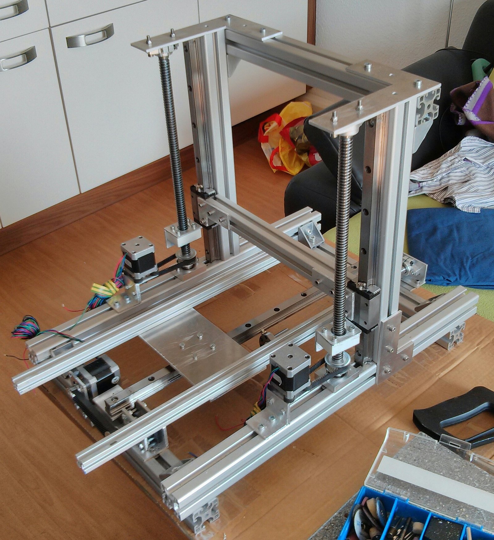
It consists of forty-millimeter aluminum system profiles connected by thick corners 45×45 and bolts M8. This design has dimensions of 60x40x40 cm and is absolutely unshakable during normal operation of the printer. The size of the working platform was 45×22 cm, the maximum height of the objects could be 28 cm.
The Z axis is formed by two vertically arranged 20 millimeter linear buses with precision carriages. The carriages are driven by precision trapezoidal screws with polymer nuts. Why the polymer: there are no high speeds / loads, and the polymer nut is not so demanding for lubrication and is much easier to install. In this construction, the height of the model is increased by raising the X axis above the table, and the Z axis is used as a movable support for the X axis.
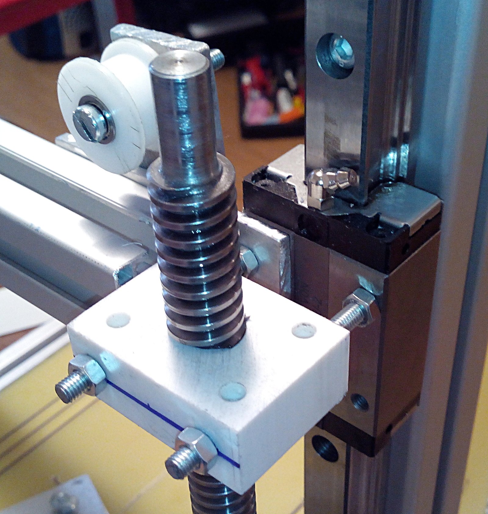
The screws were installed on the angular contact bearings, each screw Has a drive from the stepper motor through the belt transmission 1: 3. The upper ends of the screws are turned and inserted into the needle bushings so that the axial displacement of the screw in the bushing prevents its jamming during thermal expansion. Perhaps this measure is excessive, but then, under the impression of reading a lot of materials on CNC machines, it seemed to me extremely necessary.
Video of the work:
This axis Worked without any problems until disassembly of this printer for spare parts.
Disadvantages of this decision:
1. The price. Precision components are expensive.
2. Complexity of construction
3. Poor scalability.
When I started building a second printer, experience and stinginess took part in creating the design along with an innate desire to go its own way, not expecting favors from nature. Accordingly, the new printer was to become not only simpler, faster, more universal, reliable and maintainable, but also much cheaper.
For the Z axis of the new printer, a non-screw drive was chosen, and a cable structure similar to the hoist of freight cranes. It consists of the actual drive mechanism with a belt reduction gear and two blocks on which the entire mass lies along the Z axis.
Here is a photo of the printer as a whole:
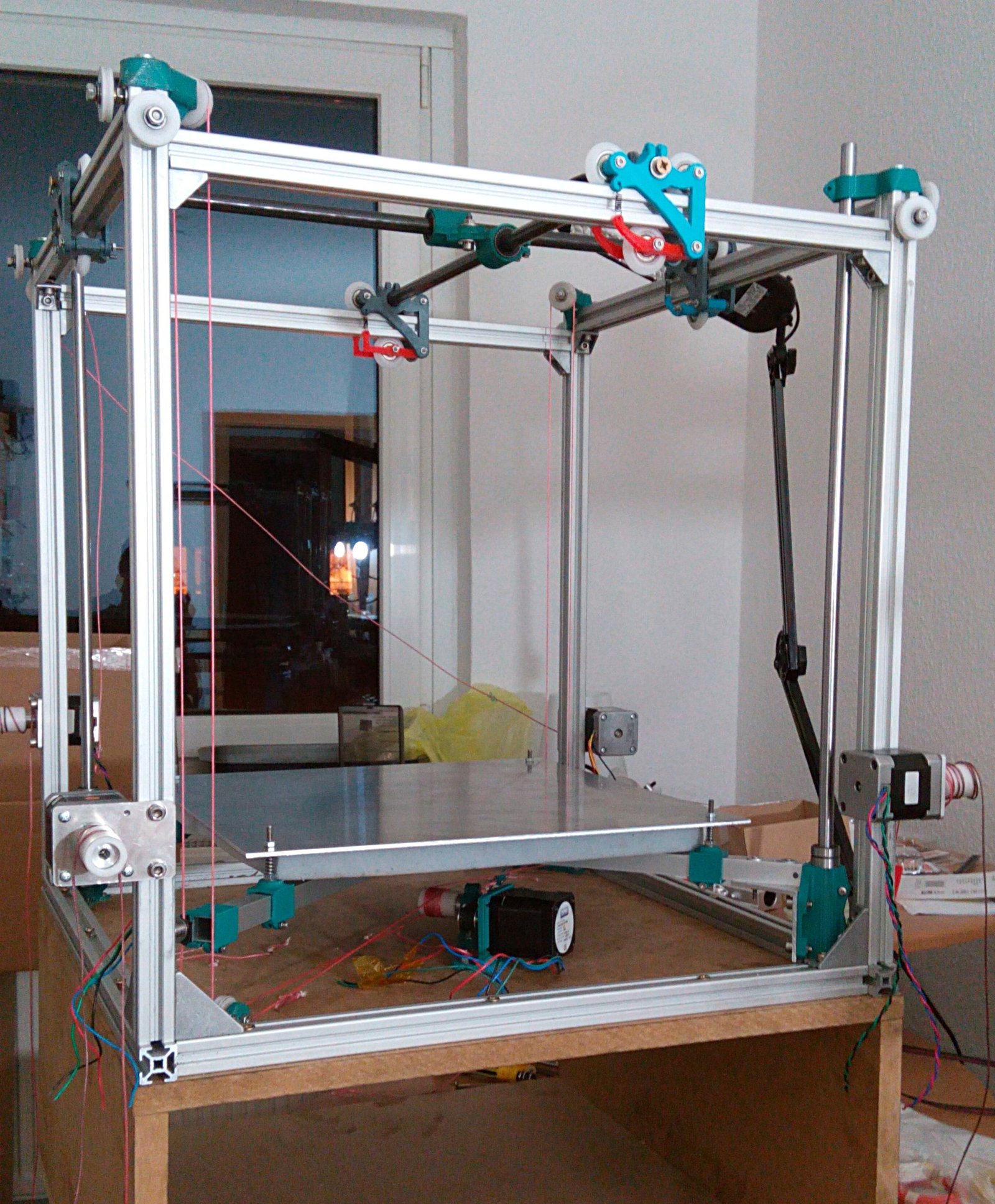
For the stability of the spatial orientation, there are two round ten-millimeter steel tires, along which the pair of plain bearing bronze sliding bearings move.
The following two videos show the construction of a winch, there is nothing complicated: there is nothing complicated there:
We go down – grow up, or the Z axis for inexpensively / Geektimes


