Firmware

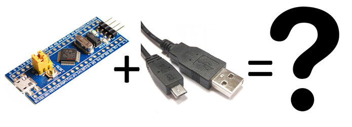
In my project, I use the STM32F103C8 microcontroller and the stm32duino framework. This clone Arduino offers a special bootloader that allows you to flash firmware via USB without using external components such as ST-Link or USB-UART adapter.
Today I needed to work with a bare CooCox controller and without stm32duino. But that’s the problem. Even a simple lavatory light bulb poured through this bootloader does not work.
Let’s deal with it. Perhaps my calculations seem to somebody a platitude. But I’m just starting to study the STM32 controllers and have killed at least a half a day searching for the problem. Suddenly this article will cut someone’s development time.
I have nothing against ST-Link and other debuggers. But in my finished device it will not be, but it will be USB. Why not immediately get the opportunity to update the firmware via USB? Personally, I find this method convenient. Especially since I already have a power cord and USB Serial connected.
Let’s see how the bootloader works. To start with the example of AVR controllers. Why did I remember it? I switched from Arduino and subconsciously expected the same behavior. But in STM32 it was all different. Therefore, I want to talk about the difference between these two microcontrollers.
So. In microcontrollers AVR ATMega under the bootloader, you can reserve a certain amount of memory near the end of the flush. With the help of fuse bits, you can adjust from which address the program will start. If there is no bootloader, the program starts from the address 0x0000. If the bootloader is – it starts from some other address (say, in ATMega32 with 0x3C00, if the size of the bootloader is 2k).

When the bootloader does his work, it passes control to the main program from the address 0x0000. Those. The program always starts from the address 0x0000. The compiler and the linker work with the fact that the code will be at the beginning of the address space.
In STM32 microcontrollers, everything is different. All programs start from the address 0x0800000. A bootloader is not that special. This is the same program that starts from the same starting address. In the process of work, the bootloader can accept the firmware (via USB or UART, read from the USB flash drive, receive it from the satellite, get it out of the subspace, whatever …) and write it to the addresses higher than the loader itself. And, of course, at the end of its work to transfer control to the main program.

So, when you compile the firmware, you need to know where the bootloader will write the firmware and adjust accordingly Addresses.
This is all about theory. Let’s move on to practice. Below is a step-by-step instruction on how to fasten the USB loader to the STM32F1xx series of microcontrollers, and maybe to some others too.
There are, however, some restrictions on circuitry. Here, unfortunately, I’m not strong. YTP needs a 1.5k pull-up resistor for the PA12 port (also USB D +). This allows the bootloader to connect and disconnect from the USB at the right time.
Instruction:
- Download github.com/rogerclarkmelbourne/STM32duino-bootloader. In the directory STM32F1 binaries there is already a package of compiled bootloaders for different boards. The index at the end of the file name indicates where the LED is connected. In the case of my board where the LED is connected to pin C13, I used the file generic_boot20_pc13.bin.
- Stitching according to the instructions. Yes, you need a USB-UART adapter, but you can probably use the debugger
- The microcontroller is now ready to be patched through the USB loader. But you still need to fix the firmware itself. And you need to do 2 things:
- The firmware flasher can be taken from the stm32duino project. In the tools directory, look for a script called maple_upload. I used only the Windows version – maple_upload.bat
- Run like this:
"maple_upload.bat" COM20 2 1EAF: 0003 "Path To Firmware.bin"Instead of COM20, you need to substitute your own port where the microcontroller has attached.The zalivator piece is very delicate, does not like relative ways. So the path to the firmware should be specified completely.
1EAF: 0003 is VID and PID
2 is the AltID parameter, which indicates that the firmware should be uploaded to the address 0x08002000 (read here)
Still a little nuance. Before you fill the firmware you need to run the bootloader. The easiest way is to press the reset button. After that, the boot loader will start and wait for a few seconds for the firmware. If at this point no one has started maple_upload, the bootloader will transfer the management of the main firmware.
To not press a reset every time, the boards based on libmaple / stm32duino use a trick. They listen to usb serial port. If there is a DTR signal and the key sequence of bytes is transmitted, the microcontroller is reloaded into the bootloader. To look in function rxHook ()
Because of it there can be an inconvenience. If the microcontroller clogs and hangs, it no longer listens to the port. Therefore, he can not hear the key sequence and reboot into the bootloader. Then only resets to the rescue.
That’s all. I hope my article will shed light on how the boot loader works in STM32 and how to download firmware via USB port. Unfortunately, the threshold of entry is still high, but suddenly someone will help my article to overcome it.


