From electronics for experiments we have:
- various microcontrollers (popular Arduino Nano, Due, less Popular but interesting Stellaris Launchpad; single-board computers Raspberry Pi 3 B + and Intel Edison)
- ADCs (AD7715, ADS7816) and DAC (DAC8512)
- Operational amplifiers: conventional and precision, low-noise
- Other electronic components for small items, as well as “donor” devices (failed ATX power supplies, UPS, CD-ROM drives, etc.)
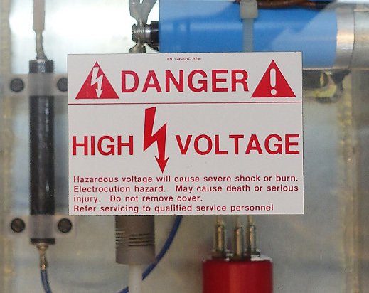
From large, independent devices there is a high-voltage power unit from an Amray microscope around 1990 of release, of unknown working capacity, with traces of repair by a Russian-speaking person.
It is necessary to understand, How to manage it, how to connect to our column and in general, check whether it works. And then suspiciously there all is signed in Russian marker:)
A small video for those who are more interested in seeing everything “live”, see how the cathode burns inside the microscope, and all this as quickly as possible:
The high-voltage power unit consists of two parts
- High voltage controlled source from 0 to -30kV
- The Aquarium
I. The source of high voltage
Stabilized, controllable, powerful enough, specially designed for electron microscopes – it’s all about it. The miracle of the technology of the 1990s, which is still produced by one American company. Voltage – 110 V, 60 Hz frequency. To my official question “will it work from 110 V 50 Hz”, sent a month ago, the company did not consider it necessary to answer. 
On the right below, and also everywhere inside, and those traces of stay are visible. Most likely, this device broke down, and was in repair. How successful was the repair – it remains to be seen.
The board on it was “bundled” with this power supply. There are no problems with it. First, it is also carefully signed by a marker, where there is +5 V, and where is 10 V. Secondly, the essence of her understanding was relatively easy.
This voltage source is controlled by an analog signal. It itself provides a reference voltage of 10 V, which corresponds to -30kV at the output. Therefore, Amray engineers have done a simple solution. Delivered a 12-bit (bit) D / A converter from which only 9 bits in the form of separate wiring were used to control, and 5 V power for the DAC. Total,
The discharge is, the power supply is switched off by overload, then turns back on again.
Since the high voltage it generates, then one wants to analyze it “quantitatively”, or, more simply, measure the output voltage.
He thought about the voltage divider rummaged all the reserves of radio components passive electronic components, or rather, mega-ohm resistors.
Found green EXPLOSIONS 
But even at the highest current divider need 30Mom. And in general, to test this source at maximum current is not an option.
I bought thirty 10MΩ resistors with a power of 1W and soldered them like this:
The paper is attracted spectacularly, and the Soviet dial gauge adds atmospheric.
But, the fact is that (and I was informed honestly by knowledgeable people), these resistors are designed for a maximum of 500 V. And in our case, the voltage drop on each one is
A fairly beautiful device, especially in comparison with oil-immersed power units of old microscopes.
The aquarium performs three main functions:
- Adjustable cathode heat
- Control of the first electrostatic lens (Venelt cylinder)
- Has a socket, which includes a high-voltage fork of the microscope:)
The difficulty is that the entire cathode is under a negative high voltage, and it is necessary to “add” the voltage necessary for the cathode to this voltage. It was apparently not fashionable to make pulsed power supplies at that time, so an alternating transformer with a motor drive was made here, and a huge transformer for mixing this voltage into the high voltage part.
The displacement voltage of the Venelt cylinder is changed by rotating a variable resistor (the simplest implementation, Because special precision is not required there).
But with a rosette there was a difficulty – it’s obviously not at all from this microscope. But, having lathes and milling machines, as well as desire, enthusiasm and a free evening, this task turns from a problem into pleasure. 
The first video in this article shows how this happened.
Well, now it’s up to the little one – to heat the cathode in its place, turn on high voltage and watch the emission of free electrons.
But, There was one more unsolved element. In the aquarium there is a board that must manage this all. The problem is that all connectors are disconnected, there is no documentation. 
I was able to guess where to connect the variable transformer of the cathode glow (in fact, this connector is the only one that obviously came up) and the input transformer into the high-voltage part (there the connector numbers differed by one, probably the extension cable was). Otherwise, I’m not sure, and the algorithm of operation is strange: one relay is on self-picking through an optocoupler, the second is simply controlled from the connector. From the tips there there are only a few inscriptions.
Perhaps fresh ideas will tell? 
Meeting in Moscow
From 11 to 13 April in Moscow in Sokolniki there will be an exhibition VacuumTechExpo (admission is free provided that you take care of an e-ticket in advance.)
Perhaps someone of you is interested and communicate with me personally? In the garage, everything can not fit :), and the exhibition presents a fairly thematic atmosphere, well suited to the project. Preferred time to write in the comments, perhaps it’s around 12:00.
Thank you for reading, always glad to read your comments to both the article and the video. Until new meetings, I hope the electron beam will also be to the next series:)
microscope microscope


